Some audio basics when working with ESP32 and INMP441 microphone
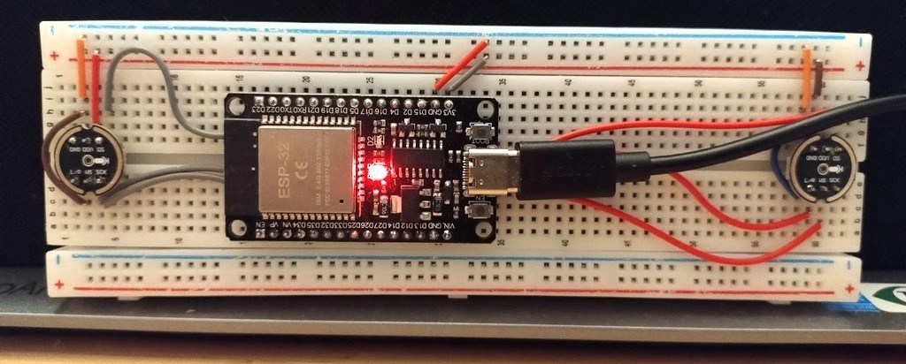
After a decade-long pause, I resumed my hobby of building robots this summer holiday. A decade ago, I was playing with Lego NXT and Arduino. This time, I am going pro with STM32 (e.g., following an STM32 course and trying FOC on STM32) and ESP32. By building, I feel alive again.
In this article for personal reference I will explain, step by step, the fundamental ideas behind digital audio, bit depth, decibels, headroom, and how they apply to the INMP441 I²S microphone and the ESP-IDF environment.
1) Sound, Amplitude, and Sampling
A microphone converts air vibrations (sound) into an electrical voltage that varies with time. To store or process that sound digitally, we measure its value many times per second—this is sampling.
- Sample rate: how often you measure the sound (e.g., 16 000 Hz = 16 000 samples per second)
- Bit depth: how precisely you represent each measurement in binary form.
Example:
- A 16-bit sample can take 65 536 possible values.
- A 24-bit sample can take 16 777 216 values.
Higher bit depth means finer detail—smaller steps between possible levels.
2) Decibels and dBFS
Because sound spans a huge range from faint to deafening, audio uses decibels (dB) to express ratios logarithmically. A decibel measures a ratio between two quantities. For power (like energy or intensity), we use:
\[\text{dB} = 10 \log_{10}\left(\frac{P}{P_{ref}}\right)\]But in audio we usually deal with amplitude (voltage, pressure, or digital sample values), and power is proportional to the square of amplitude. Therefore:
\[\frac{P}{P_{ref}} = \left(\frac{A}{A_{ref}}\right)^2\]Substituting gives:
\[\text{dB} = 10 \log_{10}\left(\frac{A^2}{A_{ref}^2}\right) = 20 \log_{10}\left(\frac{A}{A_{ref}}\right)\]That’s why the formula for amplitude uses 20 × log₁₀, while for power it’s 10 × log₁₀.
Two kinds of “dB”
There are two related but distinct uses of “dB” you will commonly see:
| Domain | Unit name | Reference point | What it measures |
|---|---|---|---|
| Acoustic (air) | dB SPL (Sound Pressure Level) | 20 µPa (threshold of human hearing) | The actual loudness of sound in the air |
| Electrical / Digital | dBFS, dBV, dBu, etc. | System-specific reference (e.g., full scale, 1 V, 0.775 V) | The signal level inside a device or file |
So when someone says “70 dB sound” they mean 70 dB above 20 µPa in the air. When we say “–6 dBFS” we mean the digital sample amplitude is half of the maximum value the system can represent. They both use decibels to express a ratio, but the reference point differs.
Acoustic dB SPL — sound in the air
Sound Pressure Level (SPL) is defined as:
\[\text{dB SPL} = 20 \log_{10}\left(\frac{p}{p_{ref}}\right)\]where p is the actual sound pressure (in Pascals) and
\[p_{ref} = 20\ \mu\text{Pa}\]Example approximate dB SPL levels:
- Breathing — ~10 dB SPL (barely audible)
- Quiet room — ~40 dB SPL
- Normal conversation (1 m away) — ~60 dB SPL
- Traffic / vacuum cleaner — ~80 dB SPL
- Rock concert — ~110 dB SPL
- Jet engine (close) — ~130 dB SPL (painful)
Digital / electrical dB — inside a system
In contrast, units like dBFS measure a digital value’s amplitude relative to the system’s maximum possible digital value (full scale):
- 0 dBFS → the largest possible sample value (clipping point)
- –6 dBFS → half amplitude
- –20 dBFS → one-tenth amplitude
The microphone links these two domains. For example, the INMP441 sensitivity spec “–26 dBFS @ 94 dB SPL” means:
94 dB SPL in the air → digital output peaks at about –26 dBFS.
This shows how many digital “steps” correspond to a given real-world loudness.
3) Dynamic Range, Quantization, and Noise
Digital samples are discrete: between two neighboring values lies a tiny rounding error called quantization noise. The finer your steps (more bits), the smaller that noise. Each additional bit doubles the number of quantization levels, halving the step size. Because doubling the signal-to-noise ratio equals a 6 dB increase (since $20\log_{10}(2) = 6.02$), every extra bit adds roughly 6 dB of potential dynamic range.
Mathematically, the ideal signal-to-quantization-noise ratio (SQNR) for an N-bit converter is: \(\text{SQNR} = 6.02 N \text{dB}\)
| Bit depth | Theoretical dynamic range |
|---|---|
| 8-bit | ~48 dB |
| 16-bit | ~96 dB |
| 24-bit | ~144 dB |
A real microphone never reaches its theoretical limit because of its analog noise floor—the random self-noise of its electronics.
4) Headroom
Headroom is the gap (in dB) between your current peak level and the clipping point (0 dBFS). Engineers leave headroom so unexpected peaks do not distort and to allow safe post-processing.
Example: if your loudest peaks are –6 dBFS, you have 6 dB of headroom.
5) Signal-to-Noise Ratio (SNR)
SNR tells how strong the desired signal is compared to the noise floor.
\[\text{SNR (dB)} = 20 \log_{10}\left(\frac{A_{signal}}{A_{noise}}\right)\]An SNR of 60 dB means the useful signal is 1 000× larger than the noise. Each 6 dB of SNR roughly equals one effective bit of precision (called ENOB, Effective Number Of Bits**).
6) One Example
Let’s take a real example of the popular INMP441 mic module. It has the following specs:
- Digital I2S Interface with High-Precision 24-Bit Data
- High SNR of 61 dBA
- High Sensitivity of –26 dBFS @ 94 dB SPL
- Flat Frequency Response from 60 Hz to 15 kHz
- Low Current Consumption of 1.4 mA
- High PSR of –75 dBFS
What these specs mean
Digital Output — 24-bit I²S: This refers to the data format, not the real analog precision. The I²S interface always transmits 24-bit words, but the lowest bits mainly carry noise rather than meaningful sound information.
SNR — 61 dBA: The Signal-to-Noise Ratio measures the difference between the microphone’s maximum signal level and its self-noise floor. 61 dBA corresponds to about 10 effective bits (ENOB) of usable precision.
Sensitivity — –26 dBFS @ 94 dB SPL: This spec says that when the microphone is exposed to a 94 dB SPL sound (about 1 Pascal of acoustic pressure, roughly the loudness of normal speech at close distance), its digital output peaks around –26 dBFS. In other words, its signal level sits 26 dB below full-scale digital clipping, giving healthy headroom for louder sounds such as shouting or music.
Frequency Response — 60 Hz to 15 kHz: The microphone’s sensitivity is nearly flat across this range, covering all important speech frequencies.
Current — 1.4 mA: The mic consumes little power, which makes it ideal for battery-powered devices.
PSR — –75 dBFS: PSR means Power Supply Rejection. It quantifies how much noise from the power line leaks into the audio signal. –75 dBFS means that power-related noise appears 75 dB below the maximum digital level—a good value indicating strong noise rejection.
So even though the INMP441 sends 24-bit numbers, only the top 10–11 bits carry meaningful sound; the lower bits are random noise. That’s why 16-bit storage loses nothing audible.
7) From Theory to Practice: ESP32 and the I²S Interface
So far, we’ve covered the theory—how sound becomes digital numbers and what those numbers mean. But how does this look in a real embedded system?
The ESP32 family of microcontrollers is widely used for audio and IoT applications. It includes a built-in I²S (Inter-IC Sound) peripheral that can capture digital audio directly from microphones like the INMP441. The I²S interface sends a steady stream of 24-bit audio words, synchronized by a bit clock (BCLK) and a word select (WS or LRCLK) signal that marks left/right or mono channels.
In ESP-IDF, we configure the I²S driver to use 32-bit slots, matching what the INMP441 outputs. The key function to capture audio is i2s_channel_read(), which fills a buffer with raw audio data from the microphone.
Here’s a practical code snippet that reads data, aligns the 24-bit sample, and converts it to 16-bit PCM:
1
2
3
4
5
6
7
8
9
10
11
12
13
#define BUF_LEN 256
int32_t raw_buf[BUF_LEN];
int16_t pcm_buf[BUF_LEN];
size_t bytes_read;

// Read I²S buffer (filled with 32-bit left-justified samples)
i2s_channel_read(i2s_rx_handle, raw_buf, sizeof(raw_buf), &bytes_read, portMAX_DELAY);

size_t samples_read = bytes_read / sizeof(int32_t);
for (size_t i = 0; i < samples_read; ++i) {
    int32_t aligned = raw_buf[i] >> 8;          // align 24-bit data
    pcm_buf[i] = (int16_t)(aligned >> 8);       // convert to 16-bit
}
Why >>8 and >>16?
- The INMP441 sends 24 valid bits, left-aligned in a 32-bit word.
>>8removes the padding (bottom 8 bits)- Another
>>8removes the least-significant 8 bits of real data, giving you a 16-bit value
This is like trimming decimal precision: 3.123455 → 3.123 — close enough for audio playback or analysis.